3 Pin Mini Xlr Wiring Diagram - Hosa Xvs 101f Mini Stereo Male To 3 Pin Xlr Female Cable 1 Feet - 3 pin xlr wiring diagram, cable wiring, etc.
byElnora Webb•
0
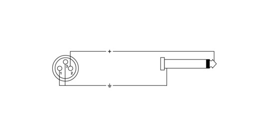
3 Pin Mini Xlr Wiring Diagram - Hosa Xvs 101f Mini Stereo Male To 3 Pin Xlr Female Cable 1 Feet - 3 pin xlr wiring diagram, cable wiring, etc.. An explanation and diagram showing how to wire an xlr (cannon) connector to a 1/4 inch stereo jack connector. 3 pin xlr wiring diagram, cable wiring, etc. The surrounding shield should be soldered to pin 1. Pin 2 on the xlr is 'hot' and carries the positive going signal, whilst pin 3 is 'cold' and provides the return. I've got a headset mic with the 4 pin shure style min xlr and need to go into a 3 pin mini xlr connection.
Xlr connector wiring diagram together with 3 pin mini 5 pin xlr wiring diagram for center u2022 4 dmx diagrams rh gregorywein co 3 female end cable wiring xlr cable wiring diagram. Pin 1 is shorted to pin 3, at either end of the cable how to wire a 1/4 jack plug (unblanced) the tip of the jack is 'hot' and carries the positive going signal, whilst the sleeve is 'cold' and carries the ground. To wire to an unbalanced twin core cable, connect the blue or 'cold' wire to the sleeve as well. Xlr to 1/4 trs connector (wired for balanced mono). Mini xlr connectors are also available with 3, 4 or 5 pins.
Mx150 User Guide from s3.us-east-2.amazonaws.com The surrounding shield should be soldered to pin 1. Go xlr app key features include: Home audio and video electronics normally use rca connectors. Visit the post for more. The pictorial shows the pin layout of a ta4f connector, as viewed from the wiring side. The above diagram shows you the pin numbering for both male and female xlr connectors, from the front and the rear view. The positive and shield of the xlr are joined together, either at the xlr end or the rca end. 3 pin xlr wiring standard.
May 21, · wiring ew sennheiser cable (cl) i have wired some mini trs to xlr male cable,(cl) to plug receivers into mixer, all the sennheisers cables was broken i had awfull noises when just touched the cable next the xlr.
3 pin xlr wiring diagram, cable wiring, etc. if you use a bright light and look at the female connector (ta4f) used for the cable, you will see numbers next to each hole. 4 pin mini xlr wiring diagram amazon microphones dynamic microphoneswh20 dynamic headset microphone wh20xlr wired includes 3 pin male xlr connector with detachable belt clip the shure wh20 is a rugged lightweight dynamic headset microphone that provides high quality voice pickup 4 pin. Xlr pin 1 to 1/4 plug sleeve. (the rear view is the end you solder from) here are the connections on each pin: To wire to an unbalanced twin core cable, connect the blue or 'cold' wire to the sleeve as well. Go xlr app key features include: Home audio and video electronics normally use rca connectors. For that transmitter and the wiring diagram for your headset mic in order to. Go xlr mini is designed for use with usb 2.0 ports. 3 pin xlr wiring diagram, cable wiring, etc. 5 pin & 3 pin xlr wiring pinout information. If you use a bright light and look at the female connector (ta4f) used for the cable, you will see numbers next to each hole. Xlr pin 2 = low impedance audio hot (amphenol pin 4, white wire, typically) xlr pin 3 = low impedance audio return (amphenol pin 3, black wire, typically) note:
Xlr pin 2 = low impedance audio hot (amphenol pin 4, white wire, typically) xlr pin 3 = low impedance audio return (amphenol pin 3, black wire, typically) note: Mini 3 pin xlr wiring diagram. Some manufacturers, especially in vintage equipment, do not follow this standard and instead reverse the polarity of pin 2 and 3. You'll also discover each xlr pin's polarity. The xlr connector is a type of electrical connector primarily found on professional audio, video, and stage lighting equipment.
3 from Any interference that penetrates the overall braided screen affects both. Audio summing allows the dual and quad receivers to function as a 2 or 4 channel mixer, respectively. Xlr pin 2 = low impedance audio hot (amphenol pin 4, white wire, typically) xlr pin 3 = low impedance audio return (amphenol pin 3, black wire, typically) note: Some manufacturers, especially in vintage equipment, do not follow this standard and instead reverse the polarity of pin 2 and 3. Xlr to 1/4 inch mono wiring diagram. Xlr pin 1 to 1/4 plug sleeve. If you use a bright light and look at the female connector (ta4f) used for the cable, you will see numbers next to each hole. 3 pin xlr wiring diagram, cable wiring, etc. cable designed for being cut into standard mic cables may have 2 pairs of wire and a shield around the outside, in that case pair the colors together and make sure they go to the same pin number on each end.
How to solder the connections for a standard 3pin xlr female.
Mini xlr wiring / 1.xlr connectors are superficially similar to the. Mx 3 pin 4 pin 5 pin mini xlr type connector is a type of connector used for many professional audio applications. 3 pin xlr connectors are standard amongst line level and mic level audio applications. Xlr to inch stereo jack plug. The positive and shield of the xlr are joined together, either at the xlr end or the rca end. Xlr pinout (balanced) a balanced system is used in pro audio systems (xlr wiring diagram shown below), with an overall screen covering a twisted pair. It is imperative for complete rf protection that the screen of the cable makes contact to the metal. Pinout of professional audio / entertainment devices 3 pin xlr connector and layout of 3 pin xlr female connector and 3 pin xlr male connectorthe xlr connectors are used mostly in professional audio and video electronics cabling applications. 3 pin xlr wiring diagram, cable wiring, etc. if you use a bright light and look at the female connector (ta4f) used for the cable, you will see numbers next to each hole. Switchcraft mini tiny xlr 3 position male solder cable xlr. If after inputting the pin code the torpedo captor x does not show up in the devices menu in torpedo wireless remote, you will need to unpair the torpedo captor x in the list of devices. However, with balanced audio you have 2 audio signals (pins #2 and #3) plus a 3rd shield/ground pin (pin #1). The pictorial shows the pin layout of a ta4f connector, as viewed from the wiring side.
Mini xlr connector wiring diagram. The pictorial shows the pin layout of a ta4f connector, as viewed from the wiring side. The connectors are circular in design and have between three and seven pins. For that transmitter and the wiring diagram for your headset mic in order to. You'll also discover each xlr pin's polarity.
Cpi Fp Rt 3 from www.cordial-cables.com 3 pin xlr wiring diagram, cable wiring, etc. cable designed for being cut into standard mic cables may have 2 pairs of. If after inputting the pin code the torpedo captor x does not show up in the devices menu in torpedo wireless remote, you will need to unpair the torpedo captor x in the list of devices. The pictorial shows the pin layout of a ta4f connector, as viewed from the wiring side. Mini xlr connectors are also available with 3, 4 or 5 pins. 3 pin xlr wiring diagram, cable wiring, etc. Xlr to inch stereo jack plug. Mini xlr wiring diagram : Xlr pinout (balanced) a balanced system is used in pro audio systems (xlr wiring diagram shown below), with an overall screen covering a twisted pair.
The xlr connector is a type of electrical connector primarily found on professional audio, video, and stage lighting equipment.
See wiring diagrams for compatibility with wireless brands. (the rear view is the end you solder from) here are the connections on each pin: 4 pin mini xlr wiring diagram amazon microphones dynamic microphoneswh20 dynamic headset microphone wh20xlr wired includes 3 pin male xlr connector with detachable belt clip the shure wh20 is a rugged lightweight dynamic headset microphone that provides high quality voice pickup 4 pin. To wire to an unbalanced twin core cable, connect the blue or 'cold' wire to the sleeve as well. The following xlr 4 pin wiring diagram photo have been authored. The easiest way is to solder a link between pins 1 and 3 (shield and negative) of the xlr, rather than trying to. The positive and shield of the xlr are joined together, either at the xlr end or the rca end. The initials xlr have nothing to do with the pinout of the connector. I've got a headset mic with the 4 pin shure style min xlr and need to go into a 3 pin mini xlr connection. Xlr pinout (balanced) a balanced system is used in pro audio systems (xlr wiring diagram shown below), with an overall screen covering a twisted pair. 3 pin xlr wiring diagram, cable wiring, etc. Xlr to 1/4 inch mono wiring diagram. The following xlr 4 pin wiring diagram photo have been authored.
(the rear view is the end you solder from) here are the connections on each pin: mini xlr wiring diagram. Cable designed for being cut into standard mic cables may have 2 pairs of wire and a shield around the outside, in that case pair the colors together.